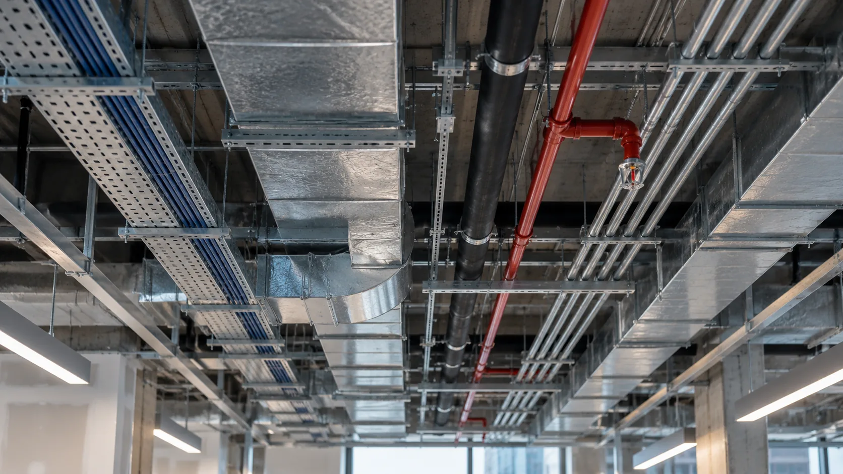
Above almost every ceiling is a contested volume, typically 300 to 600 millimeters deep, into which four or five trades must fit systems that were each designed as though the others were not there. MEP coordination is the process of allocating that volume, and MEP shop drawings are the record of the allocation.
Projects that treat this as a documentation exercise discover the conflicts on site. Projects that treat it as a spatial negotiation, run to a schedule, do not.
What MEP shop drawings comprise
The package typically includes:
Coordination drawings — composite plans and sections showing all MEP systems together with structure and ceiling, dimensioned to grid and level. These are the agreement between trades.
Trade-specific installation drawings — separate sets per trade, extracted from the coordinated model, dimensioned for installation.
Spool and fabrication drawings — duct fabrication tickets, pipe spool drawings with weld and fitting schedules, prefabricated rack and module drawings.
Hanger and support drawings — support locations, types, loads, and structural attachment, including seismic bracing where required.
Penetration drawings — sleeves and openings through structure, with sizes and locations, issued early enough for the structural trade to act on.
Equipment layouts — plant rooms, risers, and equipment with maintenance access and removal routes shown.
The priority hierarchy
Effective coordination follows a routing priority determined by physical constraint, not by trade seniority. The conventional order:
- Structure — fixed
- Gravity drainage — must fall continuously at the required gradient, with almost no routing freedom
- Large ductwork — bulky, expensive to reroute, limited fitting flexibility
- Large-bore pipe — significant but with more fitting options
- Sprinkler mains — governed by hydraulic design and head coverage
- Cable tray and busway — flexible but requires access and bend radius
- Small-bore pipe and conduit — highly flexible, routed last
Publishing this hierarchy at project start settles a large proportion of disputes before they occur. The gravity drainage position is non-negotiable and is frequently violated in early coordination attempts, producing rework in every other system.
Zone by zone, aligned to the build
Coordinating an entire building at once is a common and expensive error. It delays the first usable output until everything is complete, and it prioritizes areas that will be built last.
Instead, divide the building into coordination zones — typically a level, a wing, or a fire compartment — and sequence them to match the construction program with adequate lead time for fabrication and procurement ahead of each zone's installation date.
Each zone runs a defined cycle: model update, federation, clash test, coordination meeting, resolution, re-test, and then a formal zone sign-off in which every trade confirms the coordinated arrangement is buildable and that they will install to it. Sign-off is what converts coordination from an opinion into a commitment.
Modeling requirements that make coordination real
Coordination fails when the model omits what actually occupies space:
- Insulation thickness modeled, not assumed. Insulated pipe occupies substantially more space than the pipe.
- Hangers and supports modeled. They are frequently the actual clash.
- Valve and damper access — the swing and access envelope, not just the body.
- Duct fittings as fabricated — real radii and takeoff types, not idealized centerlines.
- Access zones for filters, coils, valves, and dampers, modeled as clearance solids so they are tested against.
- Ceiling and light fittings, including recessed depth.
- Structural fireproofing thickness where applied.
- Deflection allowance for long-span structure.
An MEP model without hangers, insulation, and access zones will coordinate cleanly and fail on site.
Fabrication output
Once a zone is signed off, fabrication output is extracted:
Ductwork — fabrication tickets by section, with gauge, seam type, reinforcement, and fitting geometry, exported to the shop's production system.
Piping — spool drawings breaking runs into shippable, weldable assemblies with weld maps, material lists, and field weld locations identified. Spool breaks should be chosen for site access and lifting capability, not only for shop convenience.
Racks and modules — multi-service prefabricated assemblies with structural frame, all services, supports, and lifting points. Prefabrication is the primary return on rigorous coordination, and it is only possible where the model is dimensionally reliable.
Hangers and inserts — coordinates for concrete inserts, issued before slab pours.
Field verification
Coordinated drawings assume the structure is where the model says it is. It frequently is not, particularly on renovation work and cast-in-place concrete.
Before fabricating, verify: actual slab soffit levels, actual column and wall positions, existing services in renovation areas, and any dimensional deviation exceeding the tolerance the coordination assumed. On refurbishment, a laser scan of the space before coordination begins is almost always cheaper than the rework it prevents.
Allocating the ceiling void
The interstitial space is a finite resource, and the projects that coordinate smoothly allocate it explicitly rather than letting trades compete for it.
A workable method is to divide the void into horizontal bands and assign each to a system category, published as a section drawing at the outset:
- Immediately below structure — the deepest elements: main ductwork and large-bore pipe, which have the least routing freedom
- Middle band — sprinkler mains, medium pipe, cable tray and busway
- Lower band — branch pipework, small-bore, conduit, and flexible connections
- Reserved zone above ceiling — lighting recess depth, access, and tile removal clearance
Crossings between bands are permitted at defined locations rather than wherever a trade finds space. This converts a free-for-all into a planned arrangement, and it dramatically reduces the number of coordination cycles required.
Where the available void is genuinely insufficient — a common finding, and one better made early — the options are structural (deeper openings, castellated or cellular beams, altered structural depth), architectural (lowered ceiling, dropped bulkheads), or systems (redesigned distribution). All three are cheap decisions in design and expensive ones in construction, which is the argument for coordinating before documentation is complete.
Renovation and existing buildings
Coordination in existing buildings differs in one decisive respect: the constraints are real rather than designed, and they are usually unknown.
The workflow that succeeds:
Scan first. Laser scan the affected zones before any coordination begins. Existing services, actual soffit levels, and structural irregularity are all captured, and the modeled result is dimensionally trustworthy.
Model what stays. Existing services remaining in service are constraints and must be modeled as such. Coordinating around an assumption about existing routing is the leading cause of rework in refurbishment MEP.
Plan the temporary condition. In occupied or phased buildings, the systems must work during construction, not only at the end. Temporary routing, isolation, and changeover sequences belong in the coordination scope.
Allow for what the scan could not see. Services within walls, above inaccessible ceilings, or below floors remain unknown. Provisional allowances and a contingency for discovery are appropriate, and stating them is better than absorbing them.
The schedule reality
MEP coordination sits on the critical path more often than any other coordination activity, because fabrication and procurement follow it. A realistic schedule allows, per zone: model preparation, two to four coordination cycles, sign-off, fabrication drawing production, submittal review, and fabrication lead time.
Compressing coordination to accelerate a program is a false economy; it converts a controlled office activity into an uncontrolled site activity at several times the cost.
Frequently asked questions
Who owns MEP coordination? Usually the mechanical contractor or a dedicated BIM coordination lead appointed by the construction manager. The role needs authority to escalate, not just to report.
How detailed must the model be? LOD 350 minimum for coordination, LOD 400 for fabrication output. Coordination attempted at LOD 300 omits exactly the elements that conflict.
Is prefabrication worth it? Where coordination is rigorous and repetition exists — hospital corridors, hotel risers, data center distribution — prefabrication reliably reduces installation time, site labor, and safety exposure. Where the model is not dimensionally trustworthy, it is a liability.
Related reading: BIM Clash Detection: Building a Workflow That Actually Resolves Clashes · The Shop Drawing Submittal Process and Why Submittals Get Rejected
Vantage CAD Services provides MEP coordination, shop drawing production, and spool and fabrication output for mechanical, electrical, plumbing, and fire protection trades. Contact info@vantagecadservices.com or +1 (512) 543-0831.