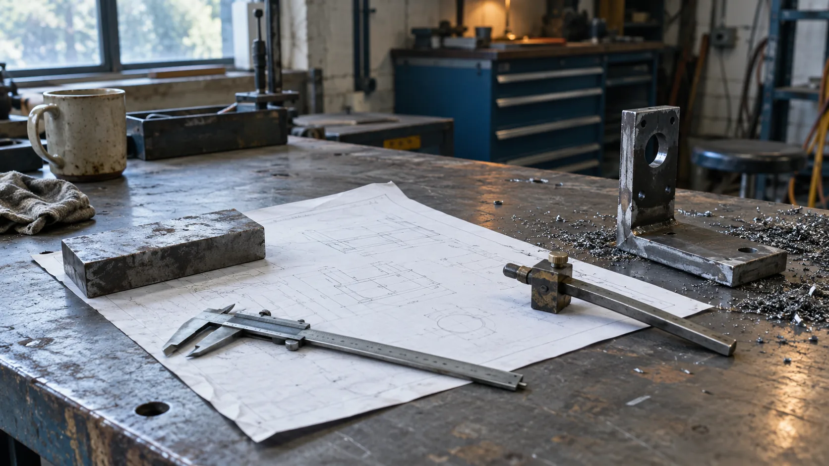
Shop drawings sit at the boundary between design and construction, and much of the friction on projects occurs precisely there. A design drawing says what is required. A shop drawing says how a specific fabricator will produce and install it. The two documents have different authors, different liabilities, and different standards of completeness — and confusing them is the source of a substantial share of rejected submittals and field rework.
Definition and purpose
A shop drawing is a detailed drawing prepared by a contractor, subcontractor, fabricator, or supplier showing how a specific portion of the work will be fabricated and installed. It translates design intent into manufacturing instruction.
Its purposes are:
- To demonstrate to the design team that the proposed fabrication satisfies the design and specification
- To provide the fabricator with dimensioned, tolerance-defined instruction for production
- To coordinate the element with adjacent trades and with actual field conditions
- To create a record of what was approved for fabrication
The last of these is under-appreciated. An approved shop drawing is a contractual record, and it is frequently the document consulted when a dispute arises years later.
How shop drawings differ from design drawings
| Design drawings | Shop drawings | |
|---|---|---|
| Author | Architect / engineer | Contractor / fabricator |
| Purpose | Define requirement | Define production |
| Scope | Whole project | One trade or element |
| Detail level | Design intent | Fabrication-ready |
| Dimensions | Nominal, design | Actual, with tolerances |
| Means and methods | Excluded | Central |
| Product data | Specified performance | Named products, actual sections |
| Field conditions | Assumed | Verified |
The dimensional distinction matters most. A design drawing may show a curtain wall bay at a nominal 1500 mm. The shop drawing shows the actual fabricated dimension accounting for surveyed field conditions, thermal movement, tolerance stack, and installation clearance. It may not be 1500 mm, and it should not be forced to be.
Which trades produce shop drawings
Practically every fabricated or assembled element:
- Structural steel — member details, connection details, erection plans, bolt and weld schedules, bills of material
- Reinforcement — bar bending schedules, placing drawings, lap and coupler details
- Precast concrete — panel geometry, embeds, lifting inserts, connection details
- Curtain wall and glazing — mullion sections, anchors, thermal breaks, gasket details
- Mechanical — duct fabrication and coordination drawings, piping spools, equipment layouts
- Electrical — panel schedules, conduit routing, cable tray, lighting layouts
- Fire protection — sprinkler head layouts, hydraulic calculations, hanger and seismic bracing
- Millwork and joinery — cabinet elevations, sections, hardware, finish schedules
- Stairs, railings, and metalwork — geometry, connections, finishes
- Elevators, storefronts, signage, specialty equipment
What a complete shop drawing contains
Regardless of trade, a shop drawing that will pass review typically includes:
Identification — project, contract, trade contractor, drawing number, revision, date, scale, and the reference design drawings and specification sections.
General arrangement — where the element sits in the building, with grid references and levels.
Detailed geometry — plans, elevations, and sections of the element with all fabrication dimensions.
Connections and interfaces — how it attaches to structure and to adjacent trades, including fixings, tolerances, and adjustment provision.
Materials and finishes — specified grades, thicknesses, coatings, and finishes, cross-referenced to the specification.
Bill of materials — quantities, marks, and cut lengths.
Fabrication and installation notes — welding requirements, tolerances, sequence, handling, and any temporary works.
Field verification statement — confirmation that dimensions were taken from site or from a coordinated model, and which.
Deviation notes — any departure from the design documents, clearly identified. Concealed deviations are the primary cause of disputes, and the fastest way for a fabricator to lose the design team's trust.
Who reviews, and what review means
The design professional reviews shop drawings for conformance with design intent and the information in the contract documents. In most standard forms of agreement, that review is explicitly not a check of dimensions, quantities, fabrication techniques, or means and methods — those remain the contractor's responsibility.
This division is frequently misunderstood in both directions. Contractors sometimes treat approval as acceptance of dimensional accuracy; designers sometimes review as though they are checking the fabricator's arithmetic. Both create liability confusion. Review stamps should state the limitation explicitly.
Typical review outcomes
- Approved / No exceptions taken — proceed to fabrication
- Approved as noted / Make corrections noted — proceed, incorporating the marked corrections, usually without resubmission
- Revise and resubmit — corrections required before fabrication
- Rejected — non-compliant, resubmit fully
- Reviewed for record only — no approval implied, typically for information items
Turnaround expectations should be stated in the contract, commonly 10 to 14 working days, and tracked in a submittal log with float built into the procurement schedule.
Why shop drawings drive the schedule
The sequence from submittal to installation is long and serial: prepare, submit, review, revise, resubmit, approve, procure material, fabricate, deliver, install. Two rejection cycles on a long-lead item can move a project completion date.
This is why shop drawing production is one of the highest-leverage places to add capacity. Faster, more accurate first submittals compress the critical path more reliably than accelerating fabrication.
Field verification: the obligation behind everything
Nearly every shop drawing carries an implicit claim: that the dimensions shown reflect the actual conditions the element will be installed into. Where that claim is untrue, the drawing is worthless regardless of how well it is drawn.
Field verification means measuring the actual space, structure, or interface after the preceding work is complete and before fabrication dimensions are fixed. Practical requirements:
Verify at the right moment. Too early, and the substrate is not finished; too late, and the fabrication schedule is compromised. This timing should be planned into the programme, not discovered.
Record what was measured, when, and by whom. A note on the drawing to this effect answers the reviewer's first question and creates the record if a dispute follows.
Measure to a datum, not cumulatively. Chained measurements accumulate error. Every dimension should reference a control line or grid.
Record deviation, not just dimension. Where the actual condition differs from the design, the drawing should show both, so the reviewer can see what is being accommodated.
Verify the interface, not only the opening. Adjacent trades' tolerances matter as much as the structure's.
On renovation and refurbishment work, laser scanning the relevant zones before shop drawing production is increasingly the default, because it produces a dimensional record that can be interrogated repeatedly rather than a set of measurements taken once.
Building a submittal package that reviews quickly
A reviewer working through a package forms an impression within the first two sheets, and that impression affects how the rest is read. Packages that review quickly share characteristics:
- A cover sheet listing contents, the specification section, and the reference drawings with their revisions
- A deviation log on page two, stating every departure from the contract documents
- Consistent sheet layout, scale, and title block across the package
- Sections cut through every distinct condition, not only the typical one
- Product data attached in the same submission, not sent separately
- Clear revision marking where this is a resubmittal, so the reviewer can focus on what changed
The deviation log is the item that most changes a reviewer's disposition. A fabricator who discloses departures reads as competent; one whose departures are discovered reads as careless, and the whole package is then scrutinised differently.
Frequently asked questions
Are shop drawings required on every project? For fabricated elements, effectively always. The specification sections name which submittals are required.
Who owns shop drawings? Ownership and use rights vary by contract. The fabricator typically retains ownership of their production information, with a license granted for project use.
Can shop drawings be produced from the BIM model? Yes, and it is increasingly standard for steel, MEP, and precast. The model must be at LOD 400 for fabrication purposes, and field verification remains necessary.
What is the most common reason for rejection? Incomplete field verification and unmarked deviation from the design documents, in that order.
Related reading: The Shop Drawing Submittal Process and Why Submittals Get Rejected · Structural Steel Detailing: From Design Model to Fabrication File · MEP Shop Drawings: Coordinating the Interstitial Space
Vantage CAD Services produces shop and fabrication drawings across structural, MEP, and architectural trades, coordinated to the model and formatted for submittal review. Contact info@vantagecadservices.com or +1 (512) 543-0831.