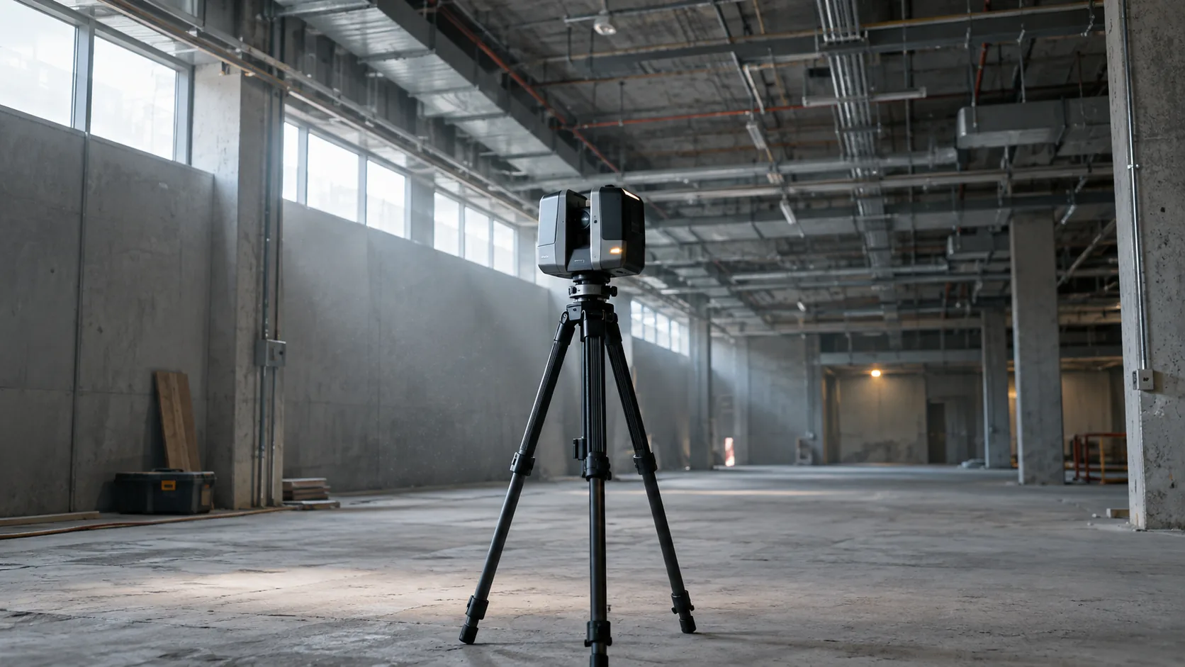
Reality capture has become inexpensive and fast. Converting what the scanner records into a model a design team can actually work in has not. The gap between a registered point cloud and a reliable Revit model is where most scan-to-BIM projects lose time, and almost all of that loss is preventable through specification rather than technique.
This article sets out the workflow end to end, with attention to the two decisions that determine whether the result is useful: tolerance and scope.
What scan to BIM is for
The purpose is not to reproduce the building. It is to produce a model accurate enough to support a specific decision — a renovation set, a clash-checked MEP retrofit, a structural assessment, an asset register, or a heritage record. Each of those needs a different model, and treating them as one deliverable is the root cause of most rework.
Before any scanning occurs, answer three questions: what decisions will this model support, what tolerance do those decisions require, and which elements matter.
Stage 1 — Capture planning
Scanning is cheap to do and expensive to redo. A capture plan should define:
- Scan positions and overlap. Typically 40–60% overlap between adjacent stations, with targets or sphere references where registration accuracy is critical.
- Control. Surveyed control points tie the cloud to a project coordinate system. Without them, a beautifully registered cloud can be confidently wrong in absolute position.
- Occlusion strategy. Ceiling voids, risers, shafts, and plant rooms need explicit attention. Above-ceiling MEP retrofits fail when the ceiling was never opened.
- Density. Higher resolution costs capture time and file size. Match resolution to the smallest element you intend to model — conduit and small-bore pipe require substantially denser capture than walls and slabs.
Stage 2 — Registration and cleaning
Registration merges individual scans into a single coordinated cloud. The registration report is the document to review, not the visual. Look for mean absolute error per cloud-to-cloud pair, overlap percentage, and the number of stations with weak constraints.
Cleaning removes transient objects — people, vehicles, temporarily stored material — and noise. It also involves segmenting the cloud by level and by zone, because a 200 GB unified cloud is unusable inside Revit even on capable hardware. Delivering per-level, per-zone indexed formats (RCS/RCP for Revit, E57 as a neutral archive) is standard practice and materially affects modeling speed.
Stage 3 — Setting tolerance
This is the decision that governs everything downstream. Tolerance is the maximum permitted deviation between the modeled element face and the point cloud surface.
Common bands:
- ±25 mm (1") — general architectural renovation, space planning, furniture and finishes coordination.
- ±10 mm (3/8") — MEP retrofit coordination, prefabrication planning, tight interstitial spaces.
- ±5 mm — structural connection verification, heritage documentation, specialist industrial work.
Tighter tolerance is not free. Moving from ±25 mm to ±10 mm typically increases modeling hours substantially, because it forces modeling of real out-of-plumb and out-of-level conditions rather than idealized geometry.
Which raises the second critical decision: idealized or as-found geometry. An idealized model shows walls plumb and slabs flat, with deviation absorbed into tolerance. An as-found model reproduces the actual warp. Renovation design usually wants idealized with recorded deviation; prefabrication and tight-fit work usually needs as-found. Specify one explicitly.
Stage 4 — Modeling sequence
An efficient sequence limits rework:
- Establish levels and grids from the cloud, then lock them. Every subsequent element hosts off these.
- Structure — columns, beams, slabs, foundations where visible. Structure defines the datum for everything else.
- Core and shell — exterior walls, roof, glazing openings, shafts.
- Interior partitions and doors — with a consistent rule for wall type assignment where construction is not visible.
- Ceilings and vertical circulation.
- MEP — mains and risers first, then branches, then terminals, then small-bore and conduit if in scope.
- Equipment and assets — modeled to the agreed LOD, with parameters populated.
Each stage should be reviewed against the cloud before the next begins. Discovering a grid error after MEP is modeled costs an order of magnitude more than discovering it after step one.
Stage 5 — Quality assurance
QA on scan to BIM has an objective method: sectional deviation analysis. Cut sections at agreed intervals — commonly every 5 m in both axes plus at each level — and compare model geometry against the cloud in each. Record deviations exceeding the specified tolerance and either correct or annotate them.
A complete QA package includes the deviation report, a list of assumed conditions where the cloud was occluded, a clash-free federated check if MEP is in scope, and a standard Revit health check (warnings, unplaced elements, purge, audit).
The list of assumptions matters more than firms expect. Every occluded area is a modeled guess, and the design team must know where those guesses are.
What to include in a scan-to-BIM brief
A brief that produces predictable results names all of the following:
- Software and version, and the template to be used
- Coordinate system and control point reference
- Tolerance band, and whether geometry is idealized or as-found
- Element scope by discipline, with LOD per element
- Minimum modeled size threshold for MEP (for example, pipe above 25 mm, duct above 100 mm, conduit excluded)
- Parameter schedule for any asset data
- Treatment of occluded and inaccessible areas
- Deliverables: model, cloud, deviation report, assumptions register, and any 2D output
Handling occlusion honestly
Every scan-to-BIM project contains areas the scanner could not see: above closed ceilings, inside shafts, behind fixed equipment, within wall build-ups, below floor finishes. What the modeler does with those areas determines whether the model helps or misleads.
Three treatments, and each should be agreed rather than assumed:
Model as assumed, flagged. The element is modeled using a reasonable assumption — typical construction, continuation of an adjacent condition — and tagged with a parameter identifying it as assumed. This is usually the right choice, because a model with holes in it is hard to use, while a model with labelled assumptions is honest and usable.
Omit entirely. Appropriate where an assumption would be actively dangerous — concealed structure that a design decision might rely on.
Model to a stated confidence level. A parameter carrying high, medium or low confidence per element, filterable in the project. This is the most useful treatment on renovation projects, because it lets a designer see at a glance which parts of the model can be relied upon.
Whichever is chosen, the assumptions register — a schedule listing every assumed condition, its location, and the basis of the assumption — should be delivered with the model. It is short, it costs almost nothing to produce, and it is the document that prevents a designer from detailing against a guess.
Cost drivers worth understanding
Scan-to-BIM pricing varies by an order of magnitude across quotes, and the variance is almost always explained by scope rather than by rate. The main drivers are tolerance, MEP inclusion and size threshold, whether as-found geometry is required, building complexity and age, and the density of small elements. A 1960s plant room and a new-build open office of identical area are not comparable scopes.
Common briefing mistakes
Requesting "an as-built model" with no tolerance. The single most expensive omission. Without a stated tolerance, the modeler either over-delivers at cost or under-delivers against an unstated expectation.
No minimum size threshold for MEP. Modeling every conduit and small-bore pipe in an existing plant room can cost more than modeling the entire building shell. State the threshold.
Scanning before deciding what the model is for. Capture density, scan positions and occlusion strategy all depend on the intended use. Scanning first and specifying afterwards frequently means returning to site.
Assuming the model will be design-ready. A scan-to-BIM model is an existing-conditions model. Converting it into a working design model — with correct wall types, room boundaries, and view templates — is a further step that should be scoped explicitly.
No provision for verification. Deviation analysis is what makes the tolerance claim meaningful. A model delivered without it is an assertion.
Frequently asked questions
Can point clouds be modeled automatically? Partially. Automated plane and pipe extraction is genuinely useful for flat surfaces and cylindrical runs, and it is improving quickly. It does not yet reliably resolve element type, hosting relationships, or occluded conditions, so a review-and-complete workflow remains necessary.
What file size should I expect? Registered clouds of a mid-size commercial building commonly land between 20 GB and 200 GB depending on resolution. Indexed and segmented delivery is what makes them workable.
Do I need the point cloud after the model is built? Yes. It is the evidence record. Retain it — deviations, disputes, and later scope additions all reference back to it.
Related reading: As-Built Drawings: How to Produce a Record Anyone Can Trust · LOD 100 to LOD 500 Explained: A Practical Reference · BIM Outsourcing: A Practical Guide for AEC Firms
Vantage CAD Services delivers scan-to-BIM modeling with documented tolerance verification and assumption registers. Contact info@vantagecadservices.com or +1 (512) 543-0831.