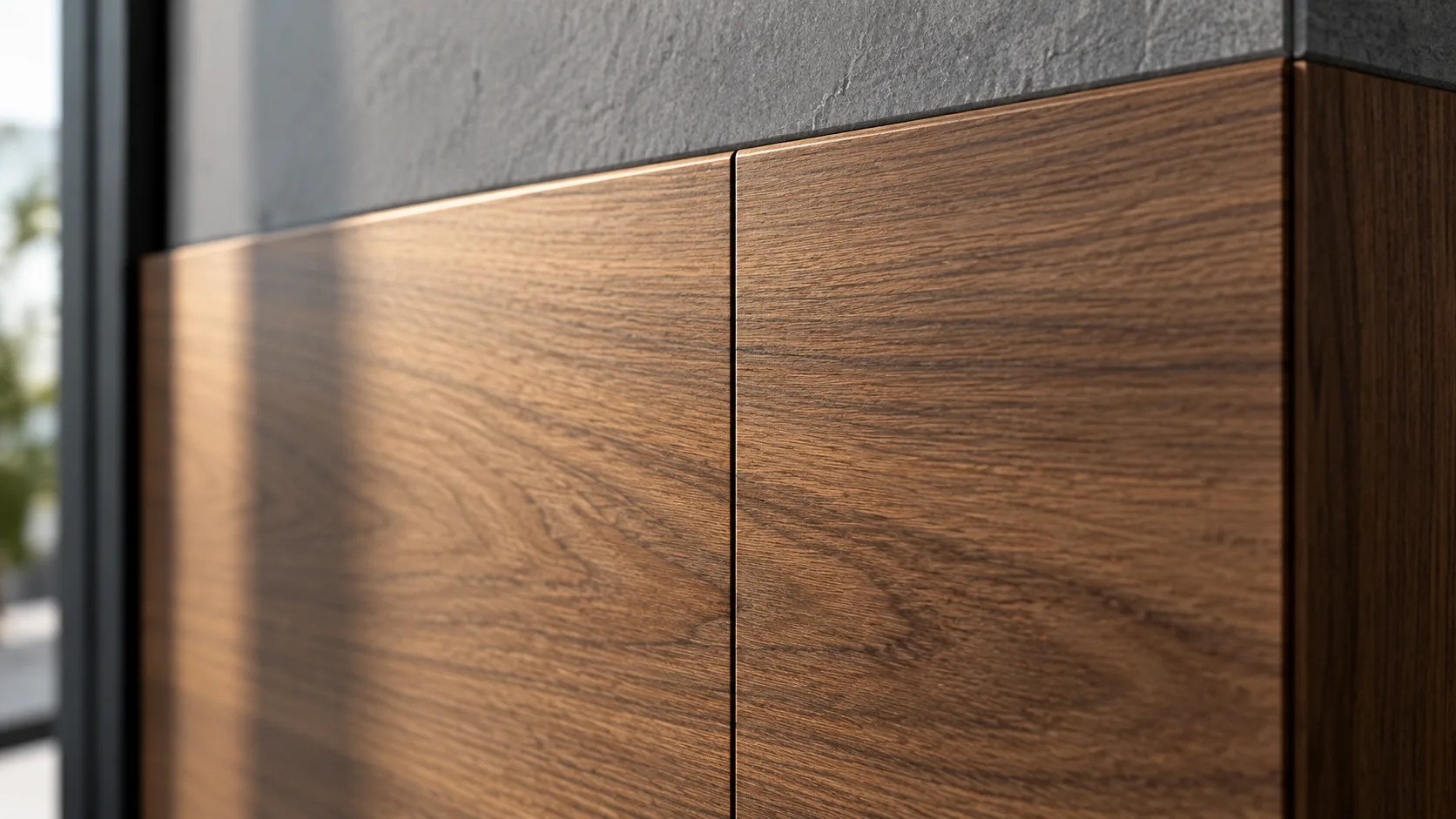
Millwork is where a project's finish quality is judged. It is also the trade where the gap between design drawing and installed reality is most visible: a reveal that varies along a run, a panel joint that lands off-center, a countertop scribed clumsily to an out-of-plumb wall.
Almost all of it is decided in the shop drawings.
Why millwork is different
Three characteristics distinguish millwork detailing from other trades.
Visible tolerance. A duct that is 12 mm out is invisible. A cabinet reveal that is 3 mm inconsistent is the first thing a client notices at handover.
Fabricated to fit a specific opening. Millwork is not a standard product installed in a nominal space. It is built to the dimensions of the actual space, which means field verification is not a formality but the basis of the entire fabrication.
Material has grain, figure, and finish continuity. Two panels of the same species are not interchangeable. Sequence and matching are design decisions that must be documented.
What the package contains
Plans — the location of every millwork item, keyed to the item numbering used throughout the package.
Elevations — every face at a scale that permits dimensioning of each door, drawer, panel, and reveal. Reveals should be dimensioned, not assumed from the drawing.
Sections — through every distinct condition: base, top, counter edge, back, and each junction between materials.
Large-scale details — typically 1:5 or 1:2 at all critical junctions, edge profiles, joints, reveals, and interfaces with adjacent construction.
Material schedule — species, cut, grade, thickness, core material, and finish for each component, with panel layout where grain matching applies.
Hardware schedule — every hinge, slide, pull, lock, catch, leg, and connector, with manufacturer, model, finish, and quantity.
Installation details — how the item attaches to the structure, including blocking requirements, shims, scribe allowances, and adjustment provision.
Coordination information — cutouts and clearances for electrical outlets, data, plumbing, appliances, ventilation, and lighting.
Finish schedule — sheen, system, number of coats, and where finishing occurs (shop or site).
Field dimensions and the scribe strategy
The dimensional strategy is the most consequential decision in a millwork package.
Millwork is fabricated to a fabrication dimension derived from a field dimension minus installation allowance. Every one of those terms should appear explicitly on the drawing.
The drawings must state:
- Whether dimensions are from design drawings or field survey, and the date of the survey
- The scribe allowance provided at each end of a run — typically 10 to 20 mm depending on wall condition and finish
- Which components are scribed on site and which are fixed
- Where filler panels absorb accumulated variance
- The permitted out-of-plumb and out-of-square condition the item can accommodate
Long runs deserve particular attention. A 12-metre reception desk against a wall that varies by 25 mm requires a deliberate plan for where that variance is absorbed. Deciding on site produces a visible defect.
Grain, sequence, and matching
Where the specification calls for matched veneer, the drawings must document it:
- Matching within a panel — book match, slip match, plank match
- Matching within a run — sequence matched, blueprint matched, or unmatched
- Grain direction — vertical or horizontal, and consistent across the elevation
- Panel layout diagram — showing which flitch panel goes where, particularly on feature walls
Sequence and blueprint matching carry significant cost and procurement lead time implications, and they cannot be recovered later. If the specification requires it, the shop drawing must show it, and the panel layout should be approved before cutting.
Standards references
North American millwork commonly references the AWI/AWMAC/WI Architectural Woodwork Standards, which define grades — economy, custom, and premium — with specific tolerance, joint, and material requirements. Specifying the grade determines permitted flushness variation, joint gaps, and finish criteria. UK and Australian projects use equivalent trade standards and, frequently, project-specific benchmark requirements.
Whatever the reference, the practical control is the benchmark or mock-up: a fabricated sample of the actual assembly, approved before production. For high-visibility work this resolves more disagreement than any amount of drawing.
Coordination that gets missed
Recurring omissions on millwork packages:
- Blocking. In-wall blocking for wall-hung items must be specified and located before the wall is closed. Discovered late, it requires opening finished construction.
- Electrical and data. Outlet positions inside cabinets, cable management, and grommet locations.
- Appliance specifications. Actual dimensions and clearance requirements of the specified units, not nominal ones.
- Plumbing. Sink cut-outs, tap hole positions, waste routing, and access.
- Lighting. Under-cabinet and integrated lighting, driver locations, and heat clearance.
- Ventilation. Clearances for equipment housed within joinery.
- Accessibility. Counter heights, knee clearance, and reach ranges where regulated.
- Fire performance. Flame-spread requirements for wall panelling in egress routes, which constrain material and finish selection.
Detailing for how it will be built and installed
A millwork drawing serves two audiences with different needs: the shop that fabricates it and the crew that installs it. Detailing that considers only the first produces items that cannot be delivered or assembled.
Fabrication considerations:
- Sheet material yield — panel layouts that minimise waste from standard sheet sizes
- Joinery method — dowel, biscuit, domino, mortise, or knock-down fittings, stated rather than left to the shop
- Edge treatment — banding material, thickness, and profile at every exposed edge
- Machining constraints — minimum radii the shop's tooling can achieve
- Finish sequence — which components are finished before assembly
Installation considerations:
- Maximum piece size that can pass through the building's doors, corridors, lifts, and stairs. Items fabricated as single units that cannot reach their destination are a recurring and expensive failure.
- Site joint locations, chosen to fall where they are least visible and detailed so they can be closed cleanly
- Weight and lifting method for heavy items
- Fixing access — whether a fixing can be reached once the item is in position
- Levelling and adjustment provision at bases and against walls
- Sequence relative to flooring, ceiling, and wall finishes
Marking site joints and maximum piece sizes on the drawings, with the access route confirmed, takes little effort and prevents the most avoidable category of millwork failure.
Review and rejection
Frequent rejection causes:
- Field dimensions not taken, or taken before the substrate was complete
- Reveals and joints undimensioned
- Hardware substituted without identification
- Material grade or matching not shown
- Junction with adjacent trades unresolved
- Deviations from the design detail incorporated without being flagged
The last of these is the most damaging to a fabricator's standing. Where a design detail is not buildable — and some are not — the correct response is to propose an alternative and mark it clearly, not to quietly build something else.
Managing the interface with adjacent trades
Millwork is installed late, into a space finished by others, and it inherits every accumulated tolerance. Managing that interface is the difference between a clean installation and a scribed compromise.
The interfaces that need explicit resolution on the drawings:
Walls and partitions. Flatness and plumb tolerance of the substrate, and how much the millwork will accommodate. A partition built to a general construction tolerance may be well outside what a flush joinery run can absorb.
Floors. Level tolerance, and whether the item sits on the finished floor or on the substrate with the finish running to it.
Ceilings. Where joinery runs to ceiling, the ceiling's tolerance and the joint detail — a shadow gap is far more forgiving than a butt joint and should be proposed where the tolerances make a butt joint unrealistic.
Services. Positions of outlets, switches, sensors, and sprinklers relative to the joinery, coordinated before either is fixed.
Stone and solid surface. Where a counter is a separate trade, the interface, support, and sequence must be agreed between them.
Raising an unrealistic tolerance expectation at shop drawing stage — proposing a shadow gap where a flush junction was drawn — is legitimate and welcome. Discovering it at installation is neither.
Frequently asked questions
When should field dimensions be taken? After the substrate is complete and finished to the state the millwork will meet: walls closed and finished, floors laid. Dimensions taken earlier will change.
Should millwork be modeled in 3D? For complex or curved work, yes — it resolves geometry that 2D sections cannot, and supports CNC output directly. Standard casework is often detailed efficiently in 2D.
Who is responsible for field dimensions? The fabricator, in almost all standard contracts. This is precisely why the shop drawing must state that they were taken and when.
Related reading: The Shop Drawing Submittal Process and Why Submittals Get Rejected · As-Built Drawings: How to Produce a Record Anyone Can Trust
Vantage CAD Services produces architectural millwork and casework shop drawings, including material schedules, hardware schedules, and CNC-ready output. Contact info@vantagecadservices.com or +1 (512) 543-0831.