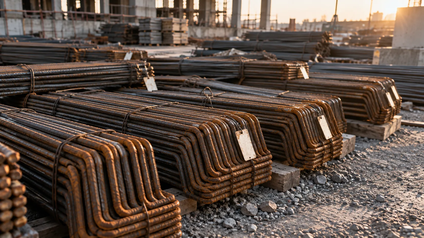
Reinforcement detailing converts a structural engineer's reinforcement design into instructions a fabricator can cut and bend to, and a steel fixer can place from. It is high-volume, standards-heavy work where small errors multiply: a lap length applied incorrectly across a floor plate produces thousands of wrong bars.
The two deliverables
Rebar detailing produces two connected outputs.
Placing drawings show where reinforcement goes. Plans, sections, and elevations with bar marks, spacing, cover, and the sequence of layers. The steel fixer works from these.
Bar bending schedules (BBS) list what to make. Every bar mark with its shape code, diameter, cut length, bending dimensions, quantity, and total weight. The fabricator works from these.
The two must agree exactly. Reconciling them is the core quality control task in the discipline, and the reason schedules generated automatically from a detailed 3D model are increasingly preferred over manually compiled ones.
What a bar bending schedule contains
A standard schedule line carries:
- Member — the element the bar belongs to (footing F1, column C3, slab S2)
- Bar mark — the unique reference used on the drawing
- Type and size — grade and diameter
- Number of members and bars per member, giving total number
- Shape code — a standardized bend geometry reference
- Bending dimensions — A, B, C, D, E, R as required by the shape code
- Cut length — the straight length of bar required before bending
- Total length and weight
Cut length is not the sum of the bending dimensions. Bending stretches the bar around the former, so cut length is derived using deductions specified by the governing standard. Applying the wrong deduction produces bars that are consistently and subtly wrong — long enough to install, wrong enough to lose cover.
Governing standards
Shape codes and bending dimensions are defined by regional standards, and they are not interchangeable:
- United States — ACI 315 detailing practice with ACI 318 design requirements; CRSI publications provide widely used industry standards for shapes, supports, and placing practice.
- United Kingdom and Europe — BS 8666 defines shape codes, bending dimensions, and tolerances, with design to Eurocode 2.
- Australia — AS 3600 for design, with AS/NZS 4671 for reinforcing materials and local detailing conventions.
A detailing brief must name the governing standard. Shape code numbering differs between them, and a schedule issued under the wrong standard will be misread by the fabricator.
Laps, anchorage, and couplers
Lap length is the most consequential single value in a reinforcement package. It depends on bar diameter, concrete grade, bar position (top-cast bars require longer laps), cover, confinement, and the proportion of bars lapped at one section.
The engineer should provide a lap length table for the project, by bar size and concrete grade, distinguishing tension and compression laps and top and bottom positions. Where this table is absent, detailing stalls or proceeds on assumption — and assumption on lap length is exactly the wrong place to guess.
Couplers are specified where laps are impractical: heavily congested sections, staged construction joints, and connections to existing structure. They must be shown explicitly on placing drawings with the manufacturer's required thread lengths and installation clearance, since a coupler that cannot be turned is not installable.
Anchorage at supports, hooks, and bends must satisfy minimum bend radii for the bar grade. Bending a high-grade bar tighter than the standard permits damages it.
Congestion — the check that gets skipped
Reinforcement congestion at beam-column joints, pile caps, transfer structures, and shear walls is the most common cause of site stoppage in concrete work. The design may be entirely correct in principle and physically impossible to build.
A congestion check verifies that:
- Bars physically fit within the section allowing for actual bar diameters, ribs, and tolerances
- Clear spacing between bars satisfies the standard and permits concrete and aggregate to pass
- Cover is maintained on all faces after all layers are placed
- The placing sequence is possible — bars can be threaded in the order required
- Vibrator access exists
- Couplers, cast-in items, embeds, and post-tensioning ducts do not occupy the same space as reinforcement
Modeling congested zones in 3D is the only reliable way to check this. Two-dimensional sections routinely show conditions that cannot exist.
Model-based rebar detailing
Detailing reinforcement in 3D — in Revit with reinforcement tools, Tekla, or a specialist package — produces several advantages that matter at volume:
- Schedules generate from the model, eliminating drawing-to-schedule discrepancy
- Congestion is visible and testable
- Quantities are reliable for procurement and cost control
- Changes propagate to every affected view and schedule
- Output can drive automated bending equipment directly
The trade-off is up-front modeling effort, which is repaid on any structure with repetition or congestion and less so on simple, low-volume work.
Quality control
A structured check on a reinforcement package covers:
Consistency — every mark on the drawing appears in the schedule with matching size, shape, and count; no orphan marks in either direction.
Cut length verification — a sample recalculated by hand against the governing standard's deductions.
Lap and anchorage — verified against the project lap table, with attention to top-cast bars.
Cover — checked on all faces including at bends and at intersections, and against the exposure class specified.
Bend radii — compliant with the standard for each bar grade and size.
Weight reconciliation — total tonnage compared against an independent estimate. A significant divergence signals a systematic error, most often a wrong bar count multiplier.
Congestion — modeled and reviewed at all critical joints.
Detailing to the pour sequence
Reinforcement is placed pour by pour, and a schedule organised by element rather than by pour creates avoidable site friction. Steel arriving as "all slab reinforcement" for a floor poured in four sections means sorting bundles on site, which is slow, error-prone, and consumes crane time.
Better practice:
Organise schedules by pour. Each pour has its own schedule and its own delivery bundle, tagged and labelled to match.
Show construction joints and starter bars explicitly. Starter bars projecting from one pour into the next are a frequent source of error — wrong length, wrong position, or omitted entirely, requiring drilling and grouting later.
Detail kicker and stitch reinforcement where it applies, rather than leaving it to site interpretation.
Coordinate with formwork. Reinforcement that cannot be placed until formwork is struck, or that prevents formwork from being struck, is a sequencing problem best identified on paper.
Identify prefabrication opportunities. Cages for piles, columns, and beams assembled off-site reduce congestion risk and placing time substantially, but require detailing that supports it — lifting points, handling stiffness, and access for the cage to be lowered into position.
Working with the fabricator
The schedule is an instruction to a specific fabrication shop, and its efficiency depends on matching that shop's capabilities.
Establish before detailing begins:
- Stock lengths available, since detailing to lengths that must be cut from longer stock generates waste that someone pays for
- Maximum bending capacity by bar diameter, and which shapes require special handling
- Minimum order quantities per bar mark, since a schedule with hundreds of single-bar marks is expensive to produce
- Tagging and bundling convention, so deliveries match the placing drawings
- Data format — many shops accept schedules directly into automated bending equipment, which removes a transcription step and its error rate
- Lead times by bar size and shape complexity
Rationalising bar marks is worth deliberate effort. A schedule with 60 marks rather than 200, achieved by standardising lengths within tolerance, is cheaper to fabricate, faster to place, and less likely to be mis-sorted on site.
Information required to start
A detailer needs: structural drawings and reinforcement design, the specification with concrete grades and exposure classes, the governing standard, the lap and anchorage table, cover requirements by element, coupler specifications, the pour sequence and construction joint locations, the fabricator's bending capabilities and standard stock lengths, and the required schedule format.
Stock length matters more than expected. Detailing to lengths a fabricator cannot supply generates unnecessary splices and waste.
Frequently asked questions
Who prepares the bar bending schedule? Usually the reinforcement supplier or a detailing specialist engaged by the contractor, working from the engineer's design. In some markets and contract forms the engineer provides it.
How accurate should tonnage be? A detailed schedule should be within a small percentage of delivered tonnage, with rolling margin and wastage allowances stated separately rather than buried in the bar quantities.
Can schedules be produced from a Revit model? Yes, provided reinforcement is modeled rather than represented, and the schedule is configured to the governing standard's shape codes and deductions.
Related reading: What Are Shop Drawings? A Complete Guide for AEC Teams · Structural Steel Detailing: From Design Model to Fabrication File · Quantity Takeoff: Manual, Digital, and Model-Based Compared
Vantage CAD Services provides reinforcement detailing, placing drawings, and bar bending schedules to ACI, BS 8666, and AS standards. Contact info@vantagecadservices.com or +1 (512) 543-0831.