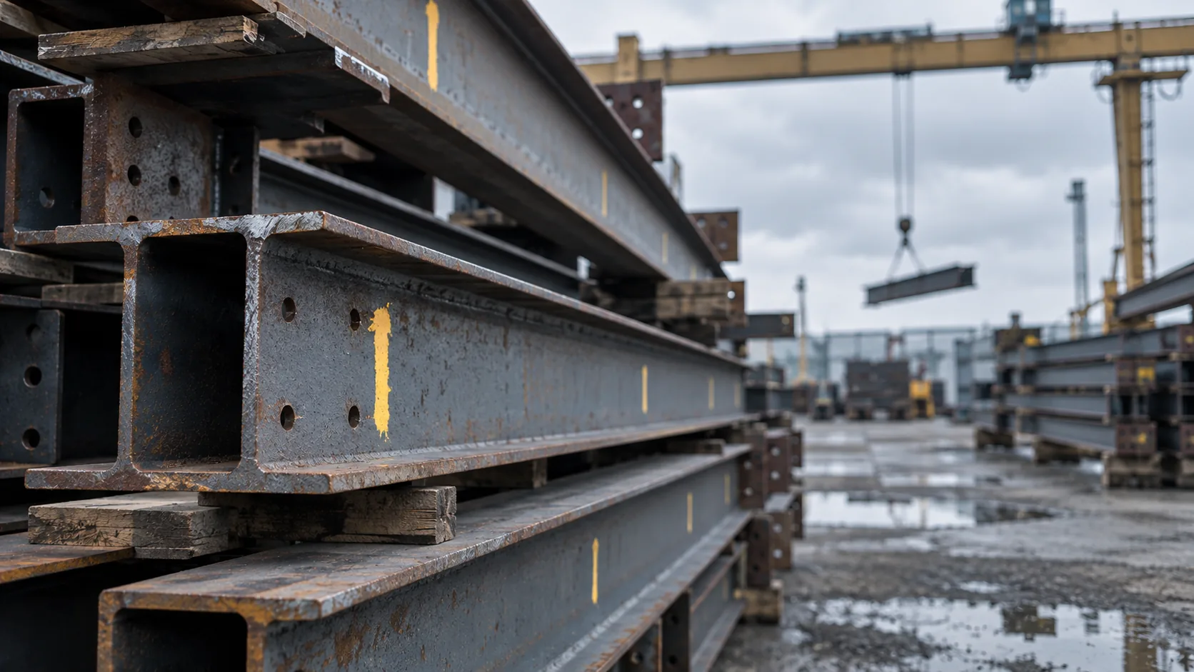
Steel detailing is the process of converting a structural engineer's design into the information a fabrication shop needs to cut, drill, weld, and ship steel, and an erector needs to assemble it. It is unusually consequential work: an error in a design drawing is corrected on paper, while an error in a detail becomes a piece of steel that arrives on site the wrong length.
This article covers the workflow, the deliverables, and the checks that keep errors out of the shop.
Where detailing sits in the chain
The sequence runs: structural design → connection design → detailing → fabrication → erection. Detailing is downstream of connection design and upstream of everything physical.
The division of responsibility for connection design is the first thing to establish on any project, because it varies:
- Engineer designs all connections and shows them on the contract drawings. The detailer models what is specified.
- Delegated connection design — the engineer specifies forces at each connection, and the fabricator's engineer designs them. This is common in the US market and requires the reaction schedule to be complete and reliable.
- Detailer selects from standard connections for simple framing, within limits and force ranges set by the engineer.
Ambiguity here causes delay. A reaction schedule that is missing, incomplete, or expressed as a percentage of member capacity without member-specific values stalls detailing entirely.
Stage 1 — Model transfer and setup
Detailing begins from the engineer's model, exported in a neutral format — IFC, SDNF, or CIS/2 — or, less efficiently, from 2D drawings alone.
The transfer is never complete. Analytical models carry centerline geometry and member sizes; they do not carry the physical detail a fabrication model needs. Expect to verify:
- Grid, level, and coordinate alignment against the architectural model
- Member sizes and grades against the schedule
- Camber requirements
- Bolt grades, hole types, and surface preparation requirements from the specification
- Corrosion protection and fire protection requirements affecting geometry
Establishing the erection mark numbering system at this point — main marks, assembly marks, and part marks — is critical, because renumbering later invalidates every drawing and shipping list already produced.
Stage 2 — Connection modeling
Connections are modeled physically, with actual plates, bolts, welds, and clearances. This is where the detailing model departs sharply from the design model.
Considerations that consistently cause problems if missed:
- Erection clearance. A connection that is geometrically valid may be impossible to assemble in sequence. Bolts need wrench access; beams need to be dropped or swung into place.
- Tolerance stack. Mill tolerance, fabrication tolerance, and erection tolerance accumulate. Slotted holes and shims are provided deliberately, not discovered on site.
- Interference with other trades. Braces, gussets, and stiffeners occupy space that MEP has often been allocated. This is a genuine clash category and should be tested against the coordinated model.
- Fabrication economy. Consistent connection types across many members are far cheaper to fabricate than individually optimized ones. A slightly heavier standard connection used a hundred times beats a hundred bespoke ones.
- Weld access and position. Shop welds are cheaper and more reliable than field welds; detailing should shift welding into the shop wherever the erection sequence permits.
Stage 3 — Drawing production
A complete steel detailing package comprises:
General arrangement / erection drawings — plans and elevations showing every member with its erection mark, orientation, and elevation, plus grid references and section marks. These are the erector's primary document.
Assembly drawings — one per assembly, showing the main member and all attached parts, with all fabrication dimensions, hole locations, weld symbols, and part marks.
Single-part drawings — for individual pieces requiring separate fabrication.
Bills of material — per assembly and per shipment, listing every part, its grade, dimensions, weight, and quantity.
Anchor bolt and embed plans — issued early, because they are on the critical path ahead of concrete work. These frequently need to be released weeks before the rest of the package.
Shipping and advance bill lists — grouping assemblies by load and by erection sequence.
CNC files — NC1/DSTV output driving beam lines, drills, and plate profiling.
Stage 4 — Checking
Steel detailing has a formal checking tradition for good reason. A structured check covers:
Model checks — clash-free within the steel model, connection completeness, no unconnected members, mark numbering unique and sequential.
Dimensional checks — every member length and hole position verified against grid and level, camber applied correctly, member orientation and rotation correct.
Specification checks — material grades, bolt grades and lengths, weld sizes and types, surface preparation, galvanizing provisions including drain and vent holes.
Coordination checks — against architectural and MEP models for penetrations, embeds, and clearance.
Erectability review — sequence walked through, access confirmed, temporary stability considered.
Independent checking by someone other than the detailer is standard practice and should not be treated as optional under schedule pressure. The cost of a check hour is trivial against the cost of remaking a fabricated assembly.
Stage 5 — Submittal and revision
Drawings are submitted to the engineer for review of conformance with design intent. Turnaround should be scheduled explicitly, since steel is usually on the critical path.
Revision control is more consequential in steel than in most disciplines because material may already be cut. Any revision after release to fabrication should carry a clear indication of what changed and whether affected pieces are already produced.
What to provide a detailing partner
To start work efficiently, a detailer needs: the structural drawings and specification, the connection reaction schedule or delegated design scope, the architectural model or drawings for coordination, the fabricator's shop capability and preferences, the erection sequence if known, the mark numbering convention, and the required output formats including CNC.
Projects that supply this set at the outset typically release anchor bolt plans within days rather than weeks.
Sequencing releases to the fabrication programme
Steel detailing is rarely delivered as one package, and how it is broken up materially affects the project programme.
A typical release sequence:
Release 1 — Anchor bolts and embeds. Required before foundations are poured, and therefore often needed weeks before the rest of the design is settled. Getting this out early requires the column layout and base plate design to be frozen ahead of everything else.
Release 2 — Main frame by area or by level. Aligned to the erection sequence, so the first steel to be erected is the first to be detailed and fabricated.
Release 3 — Secondary steel and bracing.
Release 4 — Miscellaneous metals, stairs, and platforms. Usually last, and frequently dependent on architectural information that arrives late.
Two practical consequences. First, the design information required for release 1 is a small subset of the whole, and identifying it early lets detailing start much sooner than a complete design would allow. Second, a change to the column grid after release 1 is extremely expensive, which is why anchor bolt release should be treated as a design freeze rather than a milestone.
Information flow and change management
Steel sits between a design that is still developing and a fabrication process that is unforgiving of change. Managing that boundary is most of the project management effort.
Practices that work:
A single information register. Every drawing, specification, and RFI response used, with revision and date, recorded against the detailing model. When a change arrives, the affected releases are identifiable immediately.
Formal design freeze per release. Stated in writing, with the consequence of later change acknowledged.
Change notices, not conversations. Every change to released information issued formally, with an assessment of what is already fabricated.
Fabrication status tracking. Each assembly marked as detailed, approved, released, cut, fabricated, painted, or shipped. When a change lands, the cost depends entirely on this status, and knowing it immediately determines whether the change is absorbed or contested.
Early warning on missing information. A schedule of information required, with dates, issued to the design team at the outset. Detailers who wait until they are blocked to raise a gap lose the time that early notice would have preserved.
Frequently asked questions
How long does steel detailing take? Highly variable with complexity, but anchor bolt plans are typically released first, within one to two weeks of a complete information set, with the main package following in staged releases aligned to the erection sequence.
Is Tekla required? Tekla Structures is the most widely used platform and produces CNC output natively, but SDS/2, Advance Steel, and others are in active use. The fabricator's preference generally governs.
Who is liable for a detailing error? The detailer and the fabricator carry responsibility for fabrication accuracy; the engineer's review does not transfer it. This is why independent checking matters.
Related reading: What Are Shop Drawings? A Complete Guide for AEC Teams · Rebar Detailing and Bar Bending Schedules Explained · BIM Clash Detection: Building a Workflow That Actually Resolves Clashes
Vantage CAD Services provides structural steel detailing, connection modeling, and CNC-ready fabrication output. Contact info@vantagecadservices.com or +1 (512) 543-0831.